Connect your Flow Series lighting, wire the vehicle triggers, and get connected in the BlueGhozt app.
1
Connect Your Lighting
Output 1 · Passenger Side
Connect the Flow Series components mounted on the passenger side of the vehicle.
Output 2 · Driver Side
Connect the Flow Series components mounted on the driver side of the vehicle.
Choose the Correct Power Connection
5V Flow Series
For 5V kits such as halos, DRLs, and interior dash trim kits, connect the power input to the grey 2-pin plug on the voltage regulator.
12V Flow Series
For 12V kits such as underbody lights or wheel rings, connect the power input to the grey 2-pin plug on the supplied fused wire.
Match the voltage to your LEDs. Use the appropriate regulator for 5V lighting. The connection instructions above refer to the Lighting Trendz harness; use the board diagram below when wiring controller terminals directly.
2
Connect Vehicle Triggers
Use the wire colors below to identify the trigger wires on the described harness.
Wire Color
Function
Where It Connects & What It Does
Yellow Wire
Parking / DRL
Tap into the vehicle’s existing DRL wire or an appropriate ignition source. When configured, this lets your Flow Series lighting operate with the DRL function and a startup animation.
Red Wire
Brake Light
Tap into the OEM brake light power wire to provide the brake trigger.
Green Wire
Show Mode
Connect to a toggle switch. When configured in the app, powering this trigger activates selected show modes so you can switch from your DRL setup to show lighting without opening the app.
Blue Wire
Passenger Turn Signal
Tap into the passenger-side turn signal power wire to use the sequential turn signal function.
Black Wire
Driver Turn Signal
Tap into the driver-side turn signal power wire to use the sequential turn signal function.
Wire colors and terminal labels are different references. The black wire above is the driver-side turn trigger in this harness description. Ground connections are separately labeled in the board diagram.
3
Controller Wiring Diagram
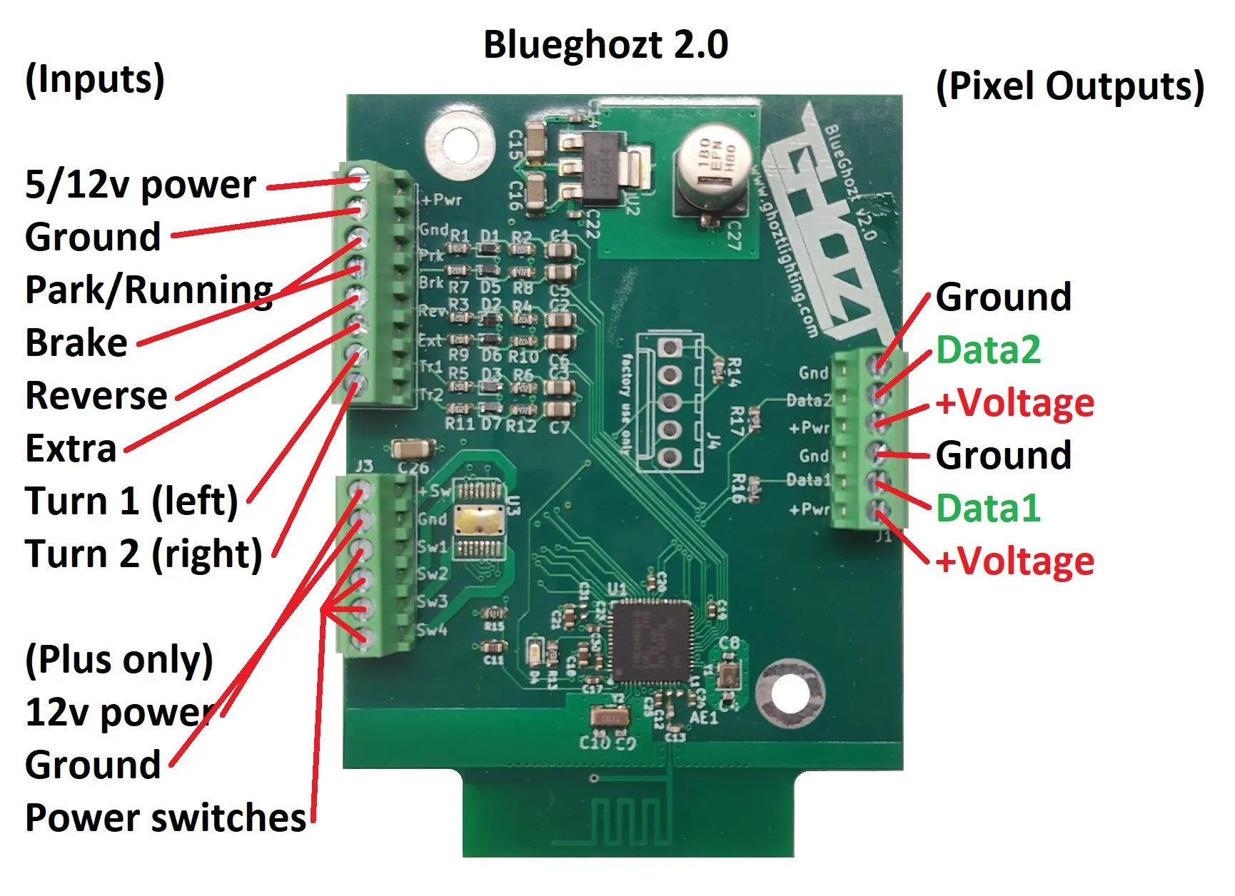
If your controller is not pre-wired, use this BlueGhozt 2.0 diagram to identify its terminals. Select the image to view it full size.
Original BlueGhozt 2.0 wiring diagram · Open full-size image
Each output group has ground, data, and +voltage connections. The diagram labels the data terminals Data1 and Data2.
Accessory Connections PLUS ONLY
Separate 12V power, ground, and four power-switch connections are shown at the lower-left terminal block.
The diagram also shows Reverse and Extra inputs. The harness wire-color list above does not specify a reverse wire color.
4
Install & Connect the App
The Bluetooth tab is where you first connect. The original screenshots below show an earlier app interface; prompts and permissions may vary by phone and app version.
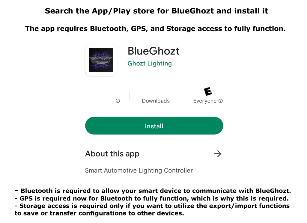
Step 1 · Install BlueGhozt
Search for BlueGhozt by Ghozt Lighting in the App Store or Google Play and install it.
Bluetooth: allows your phone or tablet to communicate with the controller.
GPS / location: the original guide calls for GPS to be enabled for Bluetooth operation. Follow the permission prompts shown on your device.
Storage: the original guide identifies storage access as needed for exporting or importing saved configurations to another device.
Original installation and permissions reference · Select to enlarge
Step 2 · Select Your Controller
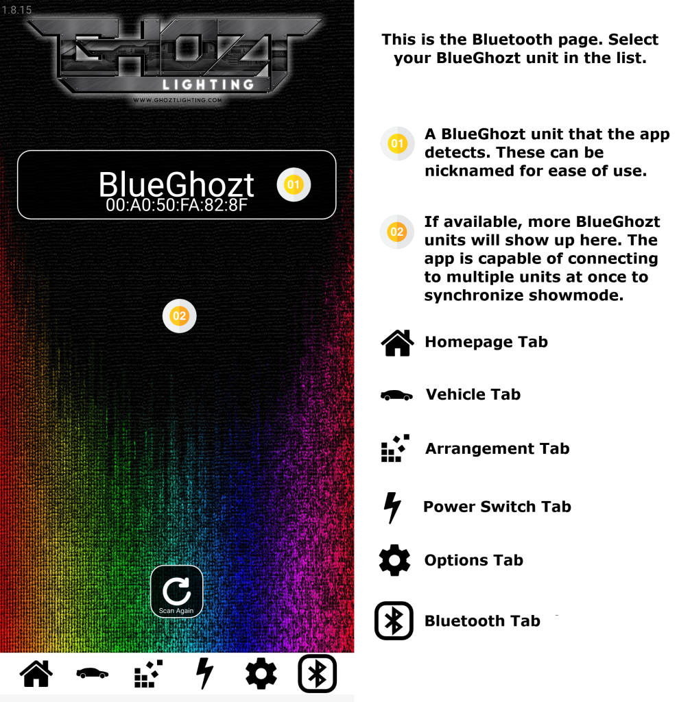
Open the Bluetooth tab and select your BlueGhozt from the detected devices.
Each detected controller appears in the list and can be nicknamed for easier identification.
Additional BlueGhozt units appear in the same list when available. The app supports connecting to multiple units to synchronize show modes.
The illustrated Scan Again button starts another scan.
Know Your App Tabs
Home · house iconVehicle · car iconArrangement · blocks iconPower Switch · lightning boltOptions · gear iconBluetooth · Bluetooth icon
Original Bluetooth tab reference · Select to enlarge
Step 3 · Set an Optional PIN
The illustrated first-connection screen prompts you to enter a four-digit PIN.
The PIN helps prevent others from connecting to your controller and changing settings at meets or events.
Select Skip if you do not want to create a PIN.
The guide says the app saves your PIN on your device so you are not prompted again.
PIN reset in the illustrated guide: if you forget the PIN or receive PIN-related access denied messages, disconnect power from the controller and reconnect it to reset the PIN. Confirm the procedure matches your controller and app version.
Original PIN setup reference · Select to enlarge
Next: Arrange Your LEDs
Once connected, configure the layout of your lighting in the Arrangement tab.