
How to Wire Your Flow Series Halos & DRLs to a Controller
Learn how to connect your compatible controller to Lighting Trendz’s 5V Flow Series halos or daytime running lights (DRLs). This guide covers Bluetooth Pro and standard Bluetooth or handheld controller setups, with wiring diagrams showing how the regulator, controller, and lights connect.
Find your controller below and follow its matching instructions. These 5V lights require a regulator—never connect them directly to a 12V power source.
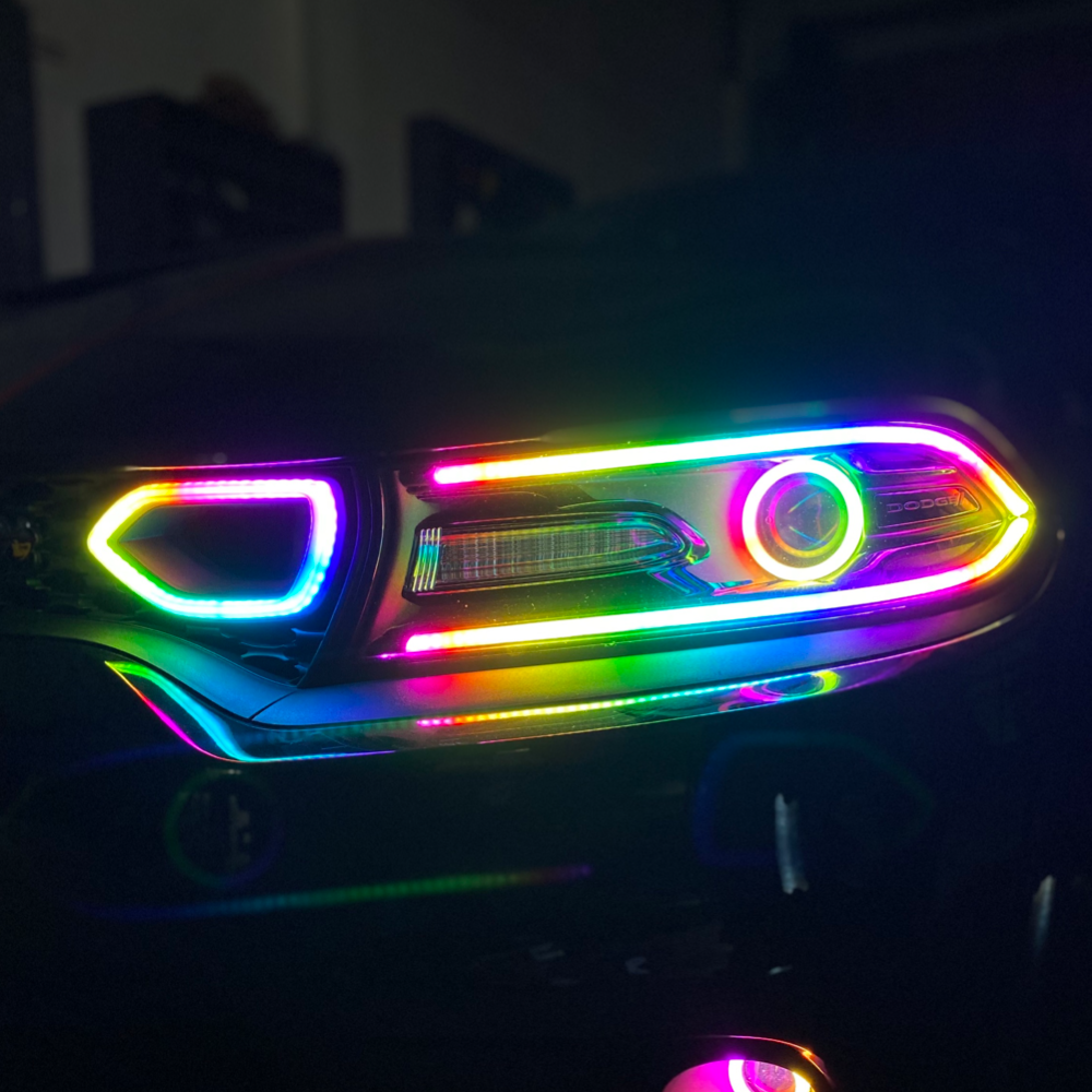
Before You Begin
These instructions cover the 5V Flow Series system described below. Check your component labels and kit instructions before connecting power.
Never connect these 5V LEDs directly to a 12V power source. The regulator reduces the vehicle’s 12V supply to the 5V required by the LEDs.
Keep power disconnected while making or changing connections. Align each connector carefully and never force plugs together.
Which Controller Are You Connecting?
Bluetooth Pro
Your halos or DRLs plug into the Pro controller’s outputs. The controller connects to the regulator.
View Bluetooth Pro wiringStandard Bluetooth or Handheld
Your controller and lights connect to the 4-output harness. The harness connects to the regulator.
View standard wiringNot sure which controller you have? Compare the components below before making any connections.
Identify Your Components
Compare your kit with the photos below. The parts you use will depend on your controller and kit configuration.
Voltage Regulator
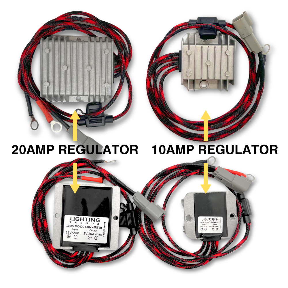
What it does: Converts the vehicle’s power supply to the 5V output required by this lighting system.
Identify yours: The 20A regulator is pictured on the left; the 10A regulator is on the right. Each is shown from both sides.
Use the regulator specified for your kit. Check the label to confirm its output voltage and current rating.
4-Output Harness
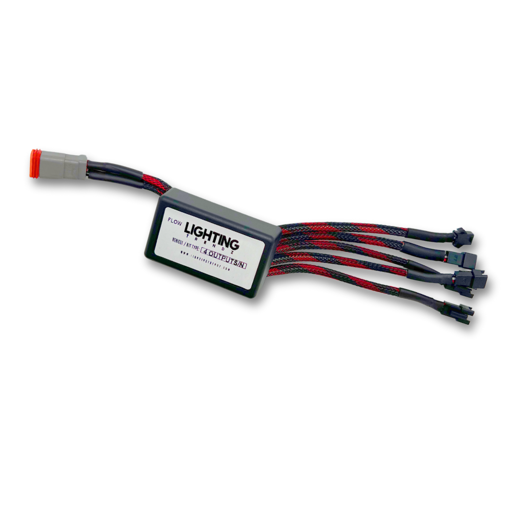
What it does: Links the regulator, controller, and LEDs in the standard controller setup, carrying power and the controller’s lighting signal.
When you use it: Follow the standard Bluetooth or handheld controller instructions for this harness. The Bluetooth Pro instructions below connect the lights to the Pro module’s outputs.
Identify the controller connection before plugging in the LEDs. Follow the connector arrangement shown in your kit’s wiring instructions.
Lighting Controller
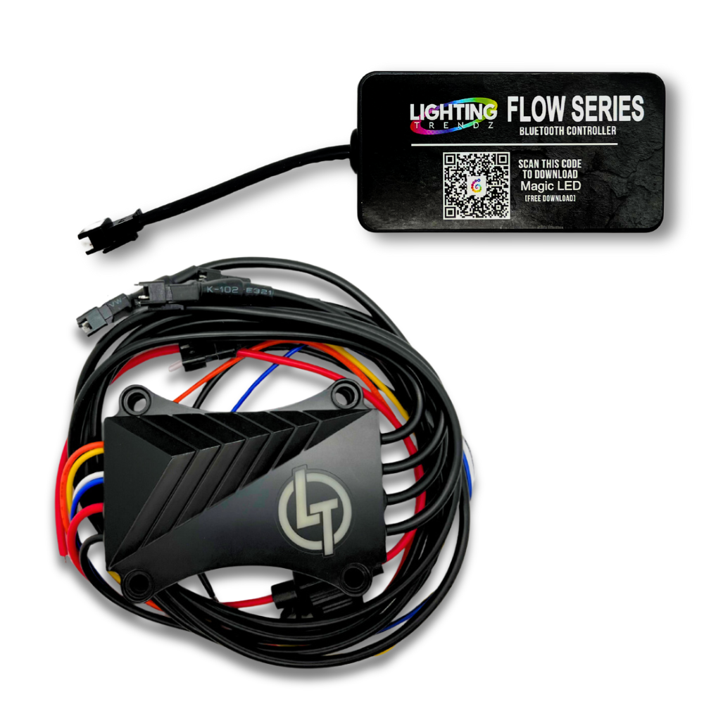
What it does: Lets you select lighting colors and patterns.
Identify yours: The upper controller is labeled “Flow Series Bluetooth Controller” and has a Magic LED app QR code. The lower module is the Bluetooth Pro controller shown in the Pro wiring diagram below. Compare the module and connectors with the controller supplied in your kit.
Use the wiring and app instructions for your exact controller model. A handheld remote is not pictured here.
Ready to connect? Continue to the Bluetooth Pro or standard controller wiring section that matches your kit.
Option 1: Bluetooth Pro Wiring
Connection layout: Regulator → Bluetooth Pro controller → halos or DRLs
Keep power disconnected while completing the connections. Use the diagram to identify each plug.
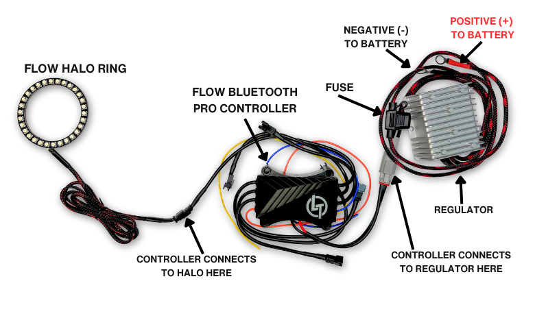 Tap to open full-size wiring diagram
- Connect the regulator to the controller. Join the matching gray connectors on the regulator and Bluetooth Pro module.
- Connect your lights. Plug the halos or DRL strips into the Pro module’s LED outputs.
- Connect optional signal inputs. Follow the function labels on your Pro module and identify the corresponding vehicle circuits before connecting them. Do not guess based on wire color.
- Connect the regulator’s power input. Identify the regulator’s positive (+) and negative (−) input leads using the diagram. Follow your kit’s power wiring instructions and confirm polarity before applying power.
- Power on and test. Check the lights and any connected signal functions before completing the installation.
Bluetooth Pro App: MotoAuto
The Bluetooth Pro controller uses the MotoAuto app. Download the app before setting up your controller, then follow the pairing instructions supplied with your module.
The Magic LED and SP105E instructions below apply to the standard SP105E controller, not Bluetooth Pro.
Option 2: Standard Bluetooth or Handheld Controller Wiring
Connection layout: Regulator → 4-output harness → controller and halos or DRLs
Keep power disconnected while completing the connections. Use the diagram to identify each plug.
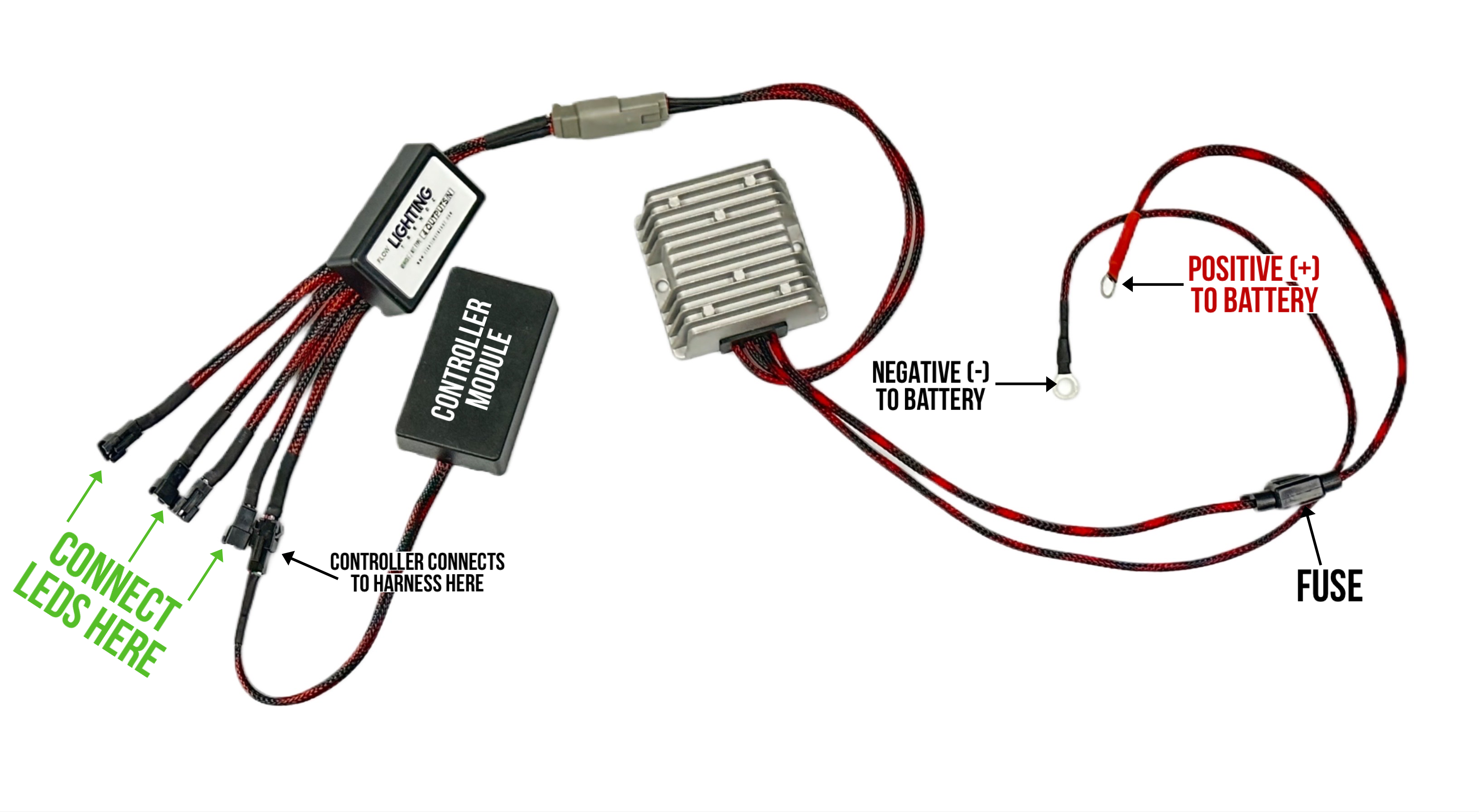 Tap to open full-size wiring diagram
- Connect the harness to the regulator. Join the supplied DT connectors.
- Connect the controller to the harness. Plug the controller module into the harness’s single female connection.
- Connect your lights. Plug the halos or DRL strips into the remaining LED connections.
- Connect the regulator’s power input. Identify the regulator’s positive (+) and negative (−) input leads using the diagram. Follow your kit’s power wiring instructions and confirm polarity before applying power.
- Power on and test. For a handheld controller, test with the supplied remote. For an SP105E Bluetooth controller, continue to the app setup below. Other models require their own pairing instructions.
After Wiring: SP105E Bluetooth Setup
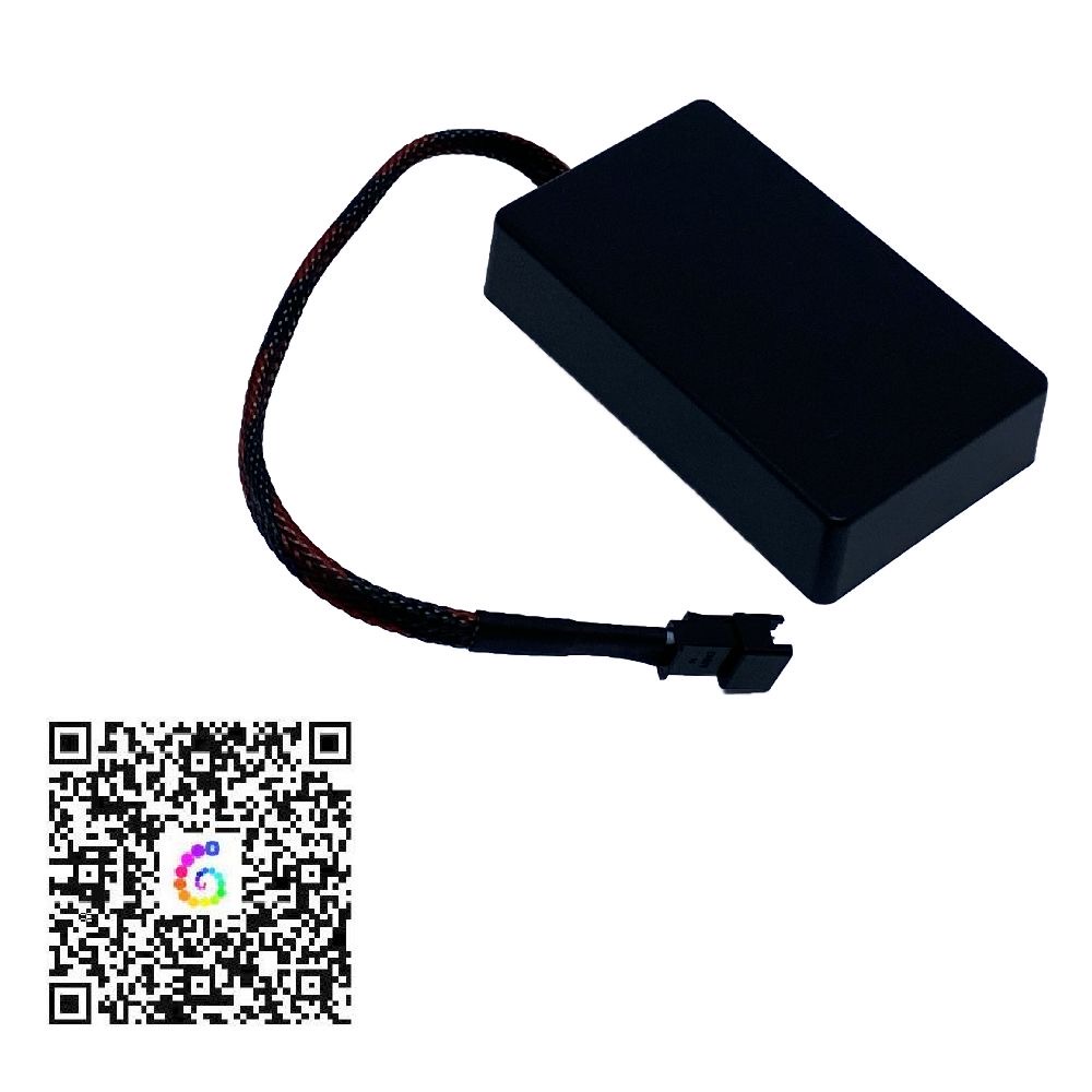
Use this section only for an SP105E controller.
- Download Magic LED using the QR code supplied with your controller.
- Turn on your phone’s Bluetooth and power on the lighting system.
- Open Magic LED and select SP105E inside the app.
- Set the color order to GRB and the LED type to SK6812-RGBW.
- Test several colors and patterns to check operation.
Troubleshooting
No lights turn on
Switch off power. Check the regulator’s input connections, polarity, and all plugs before testing again.
Only some lights work
Switch off power and inspect the connections for the affected halo or strip. Check for loose plugs or damaged wiring.
Colors do not match your selection
For the SP105E setup above, check the color order and LED type in Magic LED.
Your controller does not appear in the app
Check that the system has power, Bluetooth is enabled, and you are using the app specified for your controller.
Finish the Installation
After testing, secure the wiring away from heat, sharp edges, and moving parts. Follow your kit’s instructions for mounting components and protecting connections from moisture.
Need Help With Your Connections?
Contact Lighting Trendz with your order number, controller model, a description of the issue, and clear photos showing the regulator, controller, harness (if used), and their connections.