
INSTALLATION GUIDES / SWITCH PANELS
RGB Illuminated Switch Panel Wiring & App Instructions
Use the original wiring diagrams and app instructions to install and configure your RGB Illuminated Switch Panel.
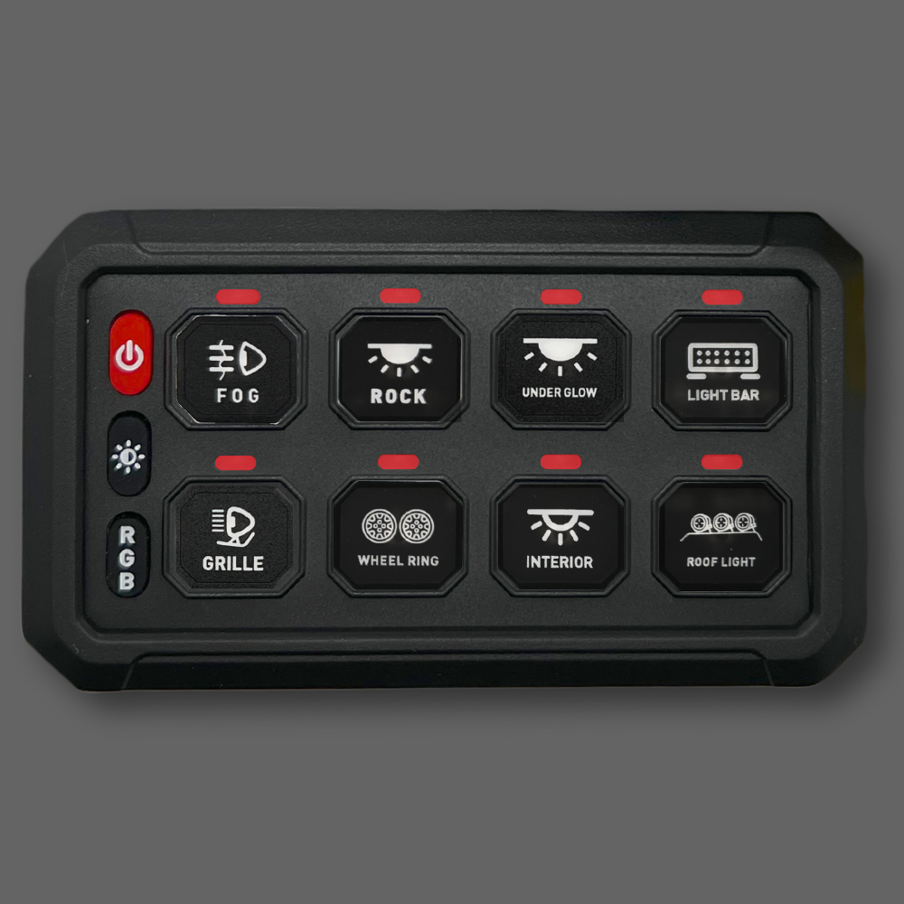
How do you set up the RGB switch panel?
Identify your panel and control box, follow the wiring diagrams for power and accessory connections, then test each circuit. Use the app manual below to connect and configure the panel’s lighting and controls.
Guide by Lighting Trendz · Updated October 27, 2026
Before You Start
- Check your panel model and supplied components against the manual. Ratings and connections vary by version.
- Disconnect power before making or changing connections.
- Keep each accessory circuit and the total load within the panel, wiring, and fuse ratings.
- Route wiring away from heat, sharp edges, and moving parts. Test the circuits before finishing installation.
Every original image is included below. Select any manual image or its full-size link to read the details in a separate tab.
Wiring Instructions
Follow these six original manual pages in order. Use the diagram that matches your panel and control box.
Wiring Manual — Page 1
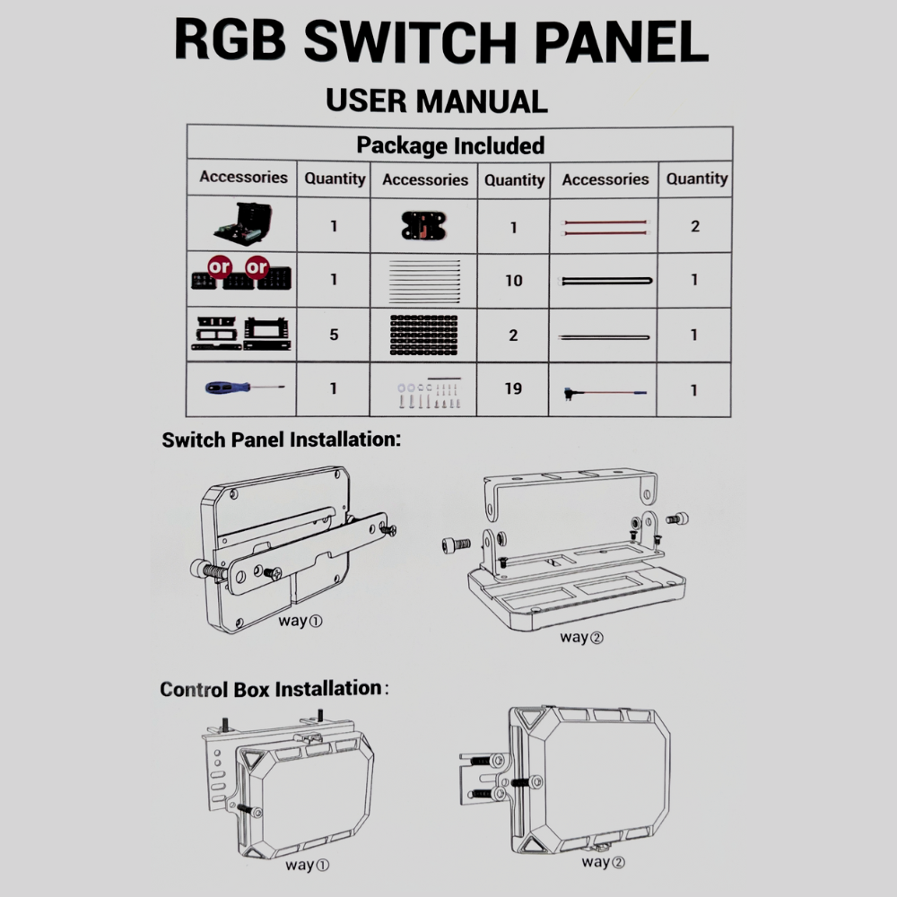
Wiring Manual — Page 2
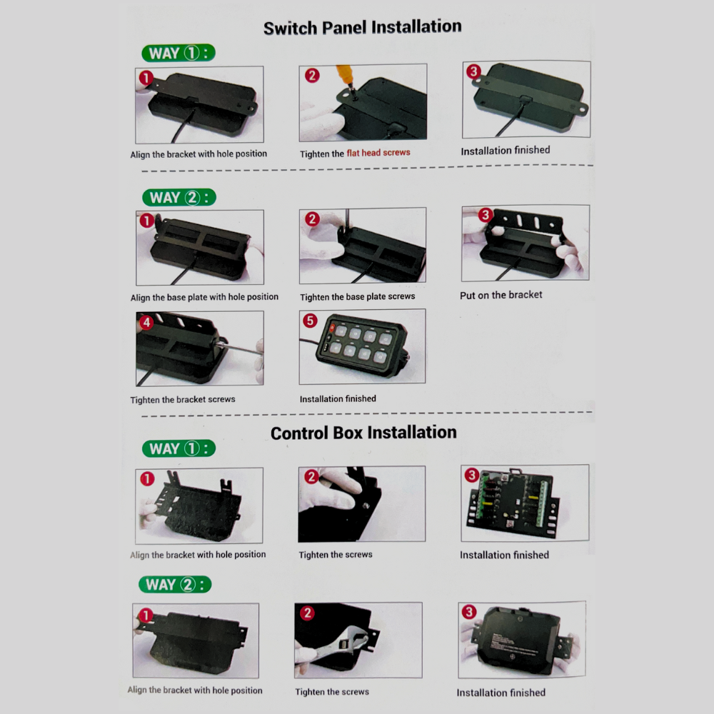
Wiring Manual — Page 3
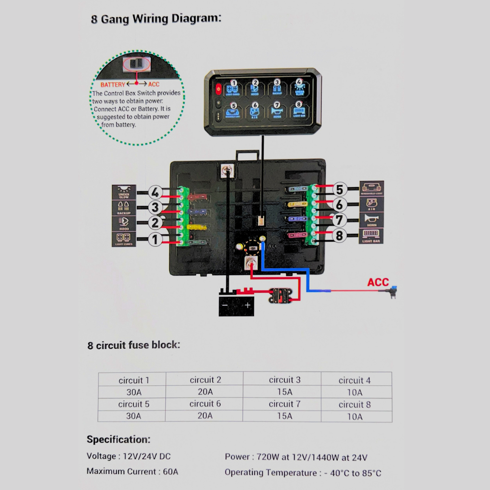
Wiring Manual — Page 4
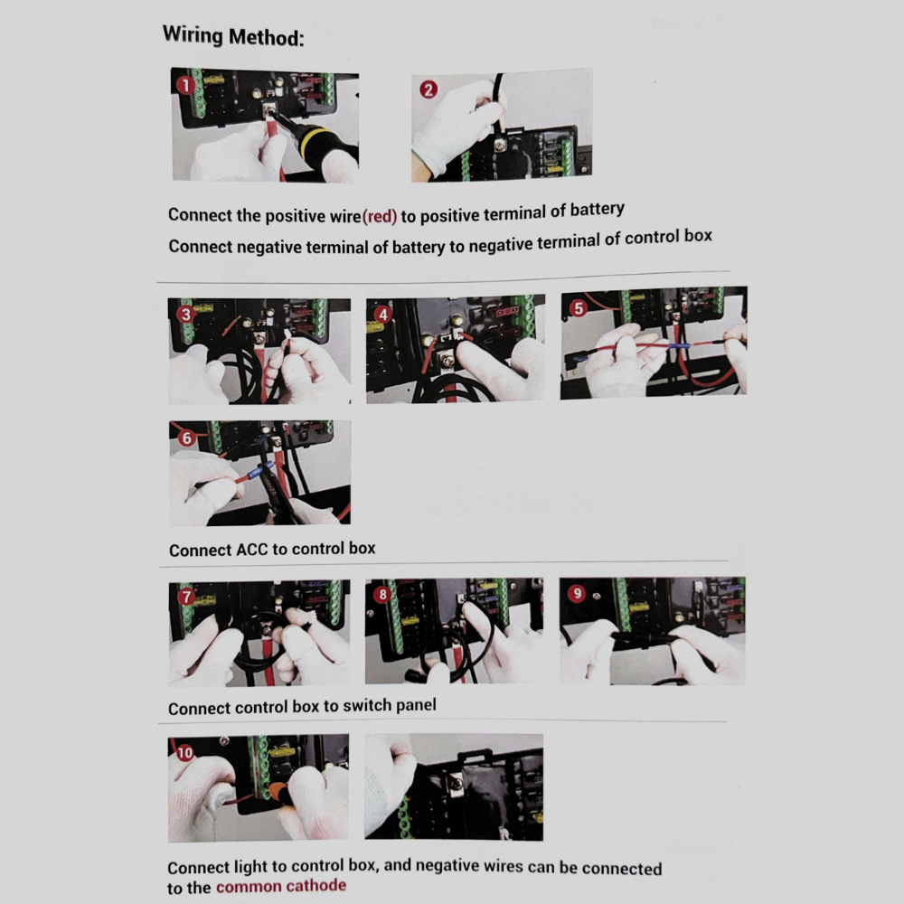
Wiring Manual — Page 5
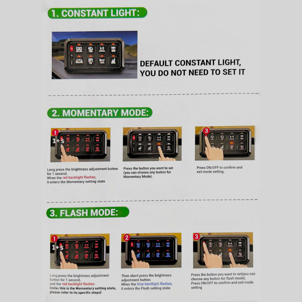
Wiring Manual — Page 6
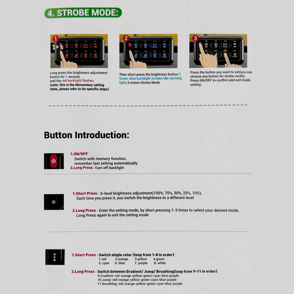
Frequently Asked Wiring Questions
How Does a Normal Switch Panel Control Two or More Lights at the Same Time with One Button?
Connect the wire from both accessories to the same positive and negative outputs of the control box. Ensure that the accessories connected to a single circuit will not draw more power than the maximum for that control box circuit and the fuse for that circuit.
Can I Connect Negative Wire to the Common Cathode?
Yes.
What Is the Maximum Running Current?
The 6-gang or 8-gang switch panel is rated for 60A, and the 12-gang is 80A.
When Connecting the Battery, the Power Indicator Is Always on, Will It Cause Battery Loss?
The guide lists standby current below 3mA. The power indicator can remain on while connected to the battery. Actual battery drain and available starting power depend on battery condition, other vehicle loads, and storage time; check the vehicle and kit instructions for long-term storage.
How Do I Know If the Wiring Is Correct?
The red power indicator confirms that the control box is receiving power. Also verify polarity, each accessory connection, fuse ratings, and operation before completing installation.
What Is the Function of the Control Box Switch?
The control box switch selects ACC or Battery operation. Follow the wiring diagram and instructions for your panel when choosing the mode.
What Is the Type of Add-a-Circuit Fuse Tap?
The original guide identifies the included tap as a small fuse tap. Confirm its exact physical fit with your vehicle’s fuse type before using it.
Can I Replace the Fuses in the Control Box?
Yes, but always use a new fuse with the SAME or LOWER amperage as the old one. For instance, replace a 30A fuse with another 30A or less; to replace a 5A fuse, do not use a 10A fuse.
Check the ratings marked on your exact model and the documentation supplied with it before connecting accessories.
App Instructions
Use the app identified in the supplied manual or QR code for your panel. Follow these eight original app-instruction pages for connecting and configuring it.
App Instructions — Page 1
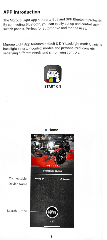
App Instructions — Page 2
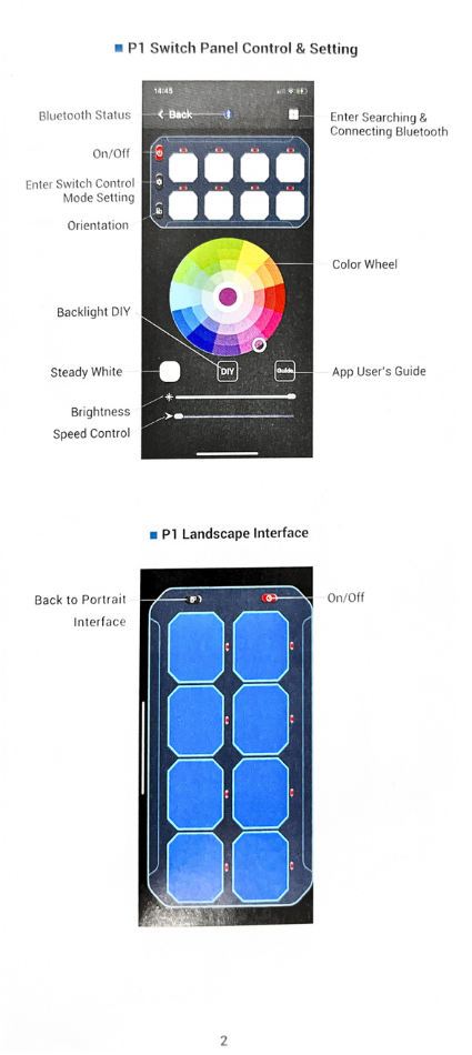
App Instructions — Page 3
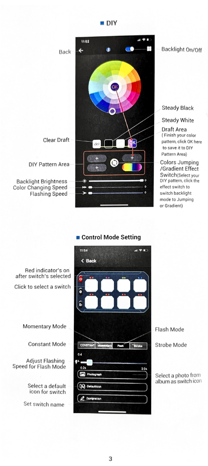
App Instructions — Page 4
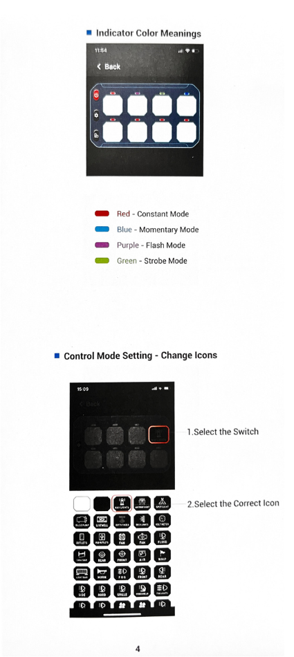
App Instructions — Page 5
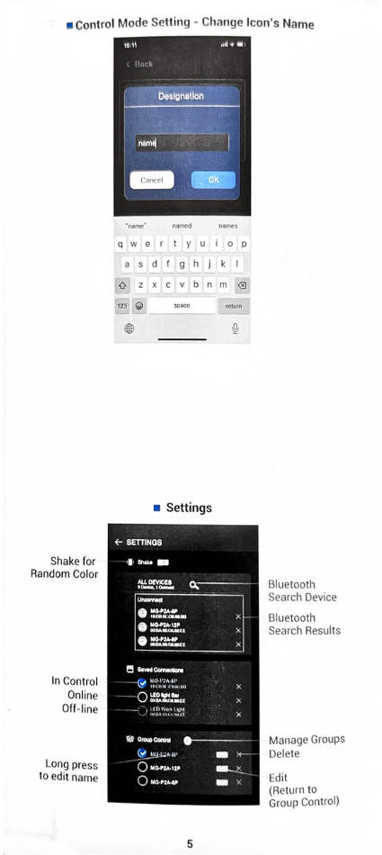
App Instructions — Page 6
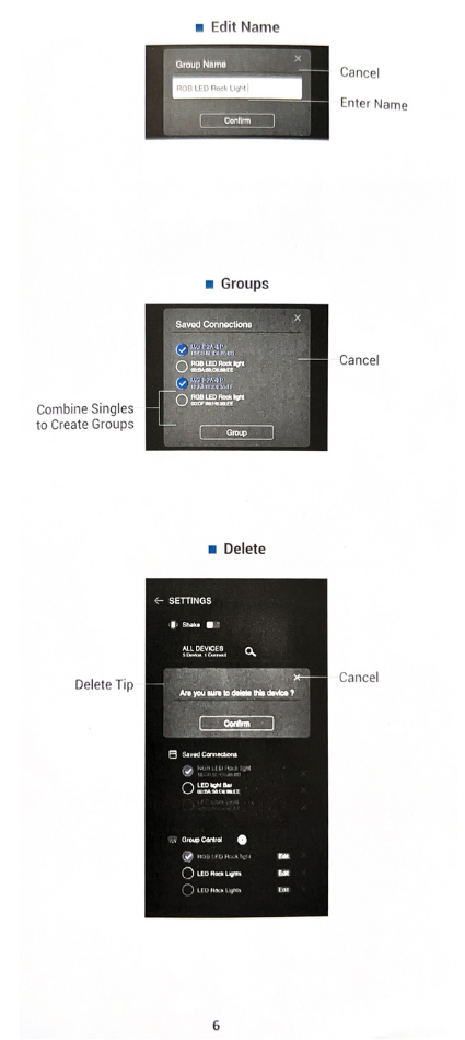
App Instructions — Page 7
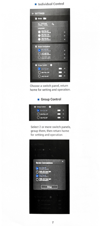
App Instructions — Page 8
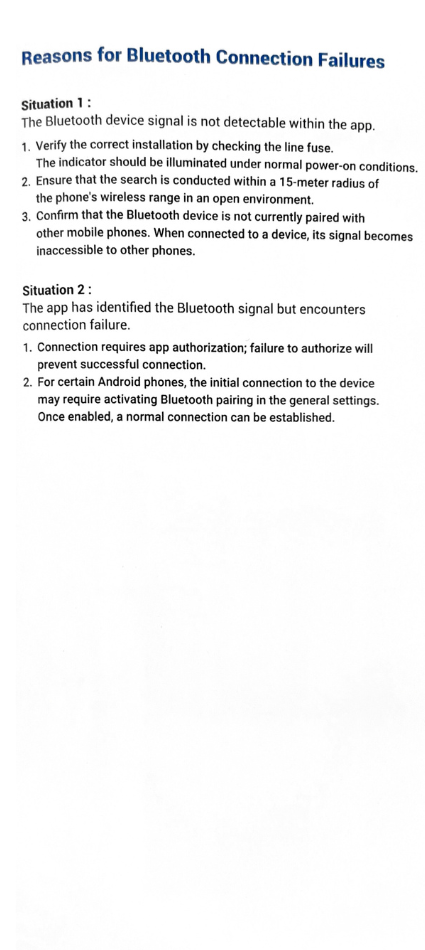
Need Help With Your Installation?
Have your panel model, vehicle details, and clear photos of the control box and wiring ready when contacting our team.