
BlueGhozt Power Switches
Wire your accessories and configure the four Power Switch outputs on BlueGhozt PLUS.
Connect Controller & Accessory Power
The Power Switches tab is available on BlueGhozt PLUS only. It configures what the four Power Switches do.
Power the BlueGhozt Controller
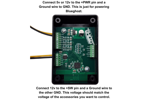
Connect 5V or 12V to the +PWR pin and a ground wire to GND. This connection powers the BlueGhozt itself.
Power the Switch Outputs
The original wiring image shows 12V connected to +SW and a ground wire connected to the other GND.
Match the accessory voltage. The +SW supply voltage should match the voltage of the accessories you want to control.
Wire Your Accessory to a Switch Output
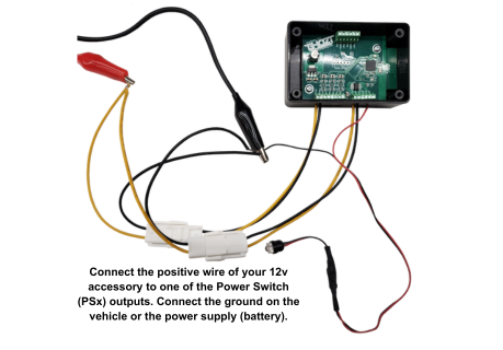
- Connect the positive wire of your 12V accessory to one of the Power Switch PSx outputs.
- Connect the accessory’s ground to the vehicle ground or the power supply / battery ground.
Note which output you used so you can test the accessory with the matching PS1–PS4 number in the app.
Get to Know the Power Switches Tab
Open the BlueGhozt app and select the Power Switches tab. Test your accessory by touching the number of the Power Switch PS1–PS4 it is wired to.
- Control type: select Basic for on/off control, PWM for dimming, or Strobe for flashes. Triggered mode is explained below.
- Number icons: turn each accessory on or off. A live ammeter displays its current use.
- Gear icon: give the Power Switch a nickname.
- Add to Home: add Power Switch shortcuts to the Home tab.
- Voltage display: view the voltage supplied to the Power Switches.
Use these controls to adjust the configuration as desired.

Choose How Each Accessory Operates
Basic · On / Off
Simply turns the connected accessory on or off.
PWM · Dimming
Adds a slider to control the brightness of the connected accessory.
PWM limitation: the original guide states that dimming will not work if a driver is connected between the Power Switch and the accessory.
Strobe · Flashing
Adds a slider to control how quickly the connected accessory flashes.
Triggered · Respond to an Input
Triggered mode has multiple uses:
- Power Cutoff Module: the original guide directs you to that module’s Getting Started page for its setup information.
- Vehicle or Showmode inputs: allow BlueGhozt to turn on a Power Switch when the selected vehicle or Showmode input is activated.
For example, an added row of 12V Superflux LEDs can turn on with the brake input when that input receives a signal.

Power Switch Setup Complete
Test your configured accessories using the number icons for each Power Switch. Watch the original tutorial below for another explanation.
Watch: Power Switches Overview
This tutorial covers Power Switches on BlueGhozt PLUS.
Next: Multisync Controllers
Learn how to connect multiple BlueGhozt controllers.